VRF Systems VR-IV Series

Features
Common features
- Greater energy efficiency
- Energy-saving functions
- Better comfort
- Design flexibility
- High reliability
- Easy installation
- Easy service and maintenance
Series Features
- Intelligent refrigerant control
- Energy saving technology that boosted operation efficiency
- Extended connection ratio
- Additional installation without changing the main pipe
- Efficiency in actual operation
- All inverter compressor
- Multiple outdoor operation control
- Heat exchanger refrigerant control
- Flexible piping connection
- Flexible installation of RB units
Outdoor unit lineup
| Space saving combination | Energy efficiency combination | |
|---|---|---|
| 8 HP | AJH072GALDH | |
| 10 HP | AJH090GALDH | |
| 12 HP | AJH108GALDH | |
| 14 HP | AJH126GALDH | |
| 16 HP | AJH144GALDH | AJH144GALDHH |
| 18 HP | AJH162GALDH | |
| 20 HP | AJH180GALDH | |
| 22 HP | AJH198GALDH | AJH198GALDHH |
| 24 HP | AJH216GALDH | AJH216GALDHH |
| 26 HP | AJH234GALDH | AJH234GALDHH |
| 28 HP | AJH252GALDH | AJH252GALDHH |
| 30 HP | AJH270GALDH | AJH270GALDHH |
| 32 HP | AJH288GALDH | AJH288GALDHH |
| 34 HP | AJH306GALDH | AJH306GALDHH |
| 36 HP | AJH324GALDH | AJH324GALDHH |
| 38 HP | AJH342GALDH | AJH342GALDHH |
| 40 HP | AJH360GALDH | AJH360GALDHH |
| 42 HP | AJH378GALDH | AJH378GALDHH |
| 44 HP | AJH396GALDH | AJH396GALDHH |
| 46 HP | AJH414GALDH | |
| 48 HP | AJH432GALDH |
Features

![]() 08:38
08:38
Intelligent refrigerant control
Fujitsu General proposes New outdoor unit which includes New refrigerant control.
New refrigerant control can be operated with suitable control corresponding to heat load of the room and can offer a more comfortable space. New refrigerant control can also provide more energy savings.

* The improvement by the control and the actual sine wave varies by the combination of the indoor unit and system operating condition.
Improvement in the number of connectable indoor units
Connectable indoor unit capacity range
New model (VR-IV) : 25%* to 150%
Current model (VR-II) : 50% to 150%
* For modular type, 25% to 49.9% operation in the entire system is available. (by one unit operation)
Connectable indoor unit number Space Saving Combination
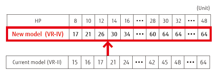
Energy-saving technologies for boosting operational efficiency

1. Large powerful propeller fan
The fan designed by using CFD*1 achieves both high performance and low-noise operation.
- *1.
- CFD: Computational Fluid Dynamics
2. 3-phase DC fan motor
The use of a DC fan motor with sophisticated driver control improves energy efficiency substantially. In addition, this motor operates quietly.
3. Sine-wave DC inverter control
The use of a motor with an intelligent power module (IPM) reduces switching loss and achieves great efficiency.
4. 4-face heat exchanger
The 4-face heat exchanger increases the effective surface area and significantly improves heat-exchanging efficiency.
5. Subcooling heat exchanger
The double-pipe structure with internal projections achieves great heat-exchanging efficiency.
6. High-efficiency, large-capacity DC inverter compressor
A high-efficiency, large-capacity DC twin-rotary compressor offers excellent intermediate capability.
7. Front slanted-corner air-intake port
When multiple outdoor units are installed, the uniquely shaped front intake improves the airflow into the heat exchanger.
Extended connection ratio (for Multi-tenant application)
This function is especially effective when partial air-conditioning starts at the building under construction. Installation work can be added flexibly for each tenant.
Current model (VR-II) Example) for 12HP: 6HP operations for 50% are required.

Current model (VR-II) Example) for 12HP: 6HP operations for 50% are required.

Modular type
One outdoor unit operates effectively for the connectable indoor unit capacity in the entire system. (25% operation by multiple units is not available.)
Example) for 25% operation (5HP) of 20HP (10HP x 2 units) 5HP operation by 50% of one 10HP outdoor unit is performed. →25% operation by 2 units is not performed.

Additional installation without changing the main pipe
Installation work can be performed from the beginning by the main pipe diameter used in the final system. Unlike current model, changing the main pipe is not necessary, so duplication of work is resolved.
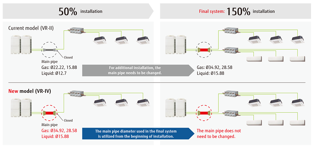
Efficiency in actual operation
Top class high COP(Max. Heating) is achieved for all combinations by our unique heat exchanger structure, high efficient DC twin compressor, and our own technologies.
Space-saving combination

Energy-efficient combination
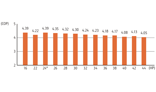
For 24-HP combination

All-inverter compressor
Large-capacity DC inverter compressor
A high-efficiency, large-capacity DC twin-rotary compressor offers excellent intermediate capability.

Multiple outdoor operation control
When multiple outdoor units are connected a sophisticated operation is performed by each compressor. Rather than running one compressor at full load and distributing refrigerant to one heat exchanger, this control method operates all compressors at part load and distributes refrigerant to all of the heat exchangers which allows for the overall system efficiency to be improved.

Heat exchanger refrigerant control
The heat exchanger in the outdoor unit is split into two parts (Top and Bottom). The efficiency of the heat exchanger has been improved by adopting an optimum refrigerant path control where the refrigerant is distributed more into the top heat exchanger as this is where there is a greater airflow intake.

Flexible piping connection
The use of various piping and RB Unit connections enables flexible refrigerant piping work that matches the floor layout and building structure.
- An RB Unit can be placed between the first branch and an indoor unit.
- The maximum height difference between RB Units is 15 m.

*1. No RB Unit is required for cooling-only use.
Flexible installation of RB units
Small & slim design saves space. Height 198 mm!
- A drain pipe is not required
- The control box position can be changed to meet the installation conditions
- Simple installation series connection design
Single-Port RB-Box:
Installation freedom

The electric control box can be installed on both sides of the RB unit!

The electric control box can be installed on top of the RB unit!
4-Port RB-Box:

2 sets of connection terminals for greater flexibility

Two RB Units can be connected in series.
8/12-Port RB-Box:
Easy to maintain in tight spaces
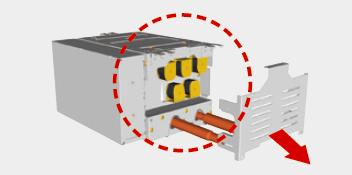
Maintenance can be performed from the side.
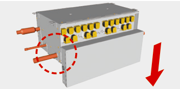
An electrical box can be accessed and serviced by sliding down the front cover.
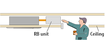
Parts can be accessed and replaced easily even in tight spaces inside the ceiling.
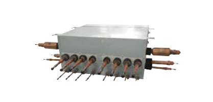
RB unit (Multi-split type/8-branch)
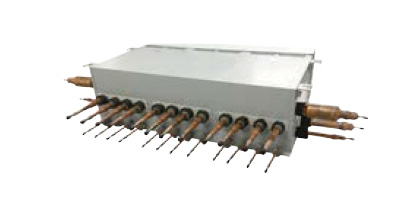
RB unit (Multi-split type/12-branch


 Europe | English